Assembly
These assembly instructions are not like a manual that cares about each step. To follow these instructions we are assuming that you will figure out the best way to perform each step.
For example, we will say "fix the H bridge driver at the chassis". Then you can fix it using screws, glue, tape... No matter.
Each step is listed bellow, you may click at a specific step or scroll down to see each one:
- Motor preparation
- Chassis preparation
- Motor and IR sensor fixation
- Battery and motor driver positioning
Motor preparation
The motor plastic support was made to be fixed within a plate, but we needed to put the motor away from the chassis. So to fix the motors with the extensors on the chassis some plates from old CDs were made.
The image bellow shows the result of motor preparation:
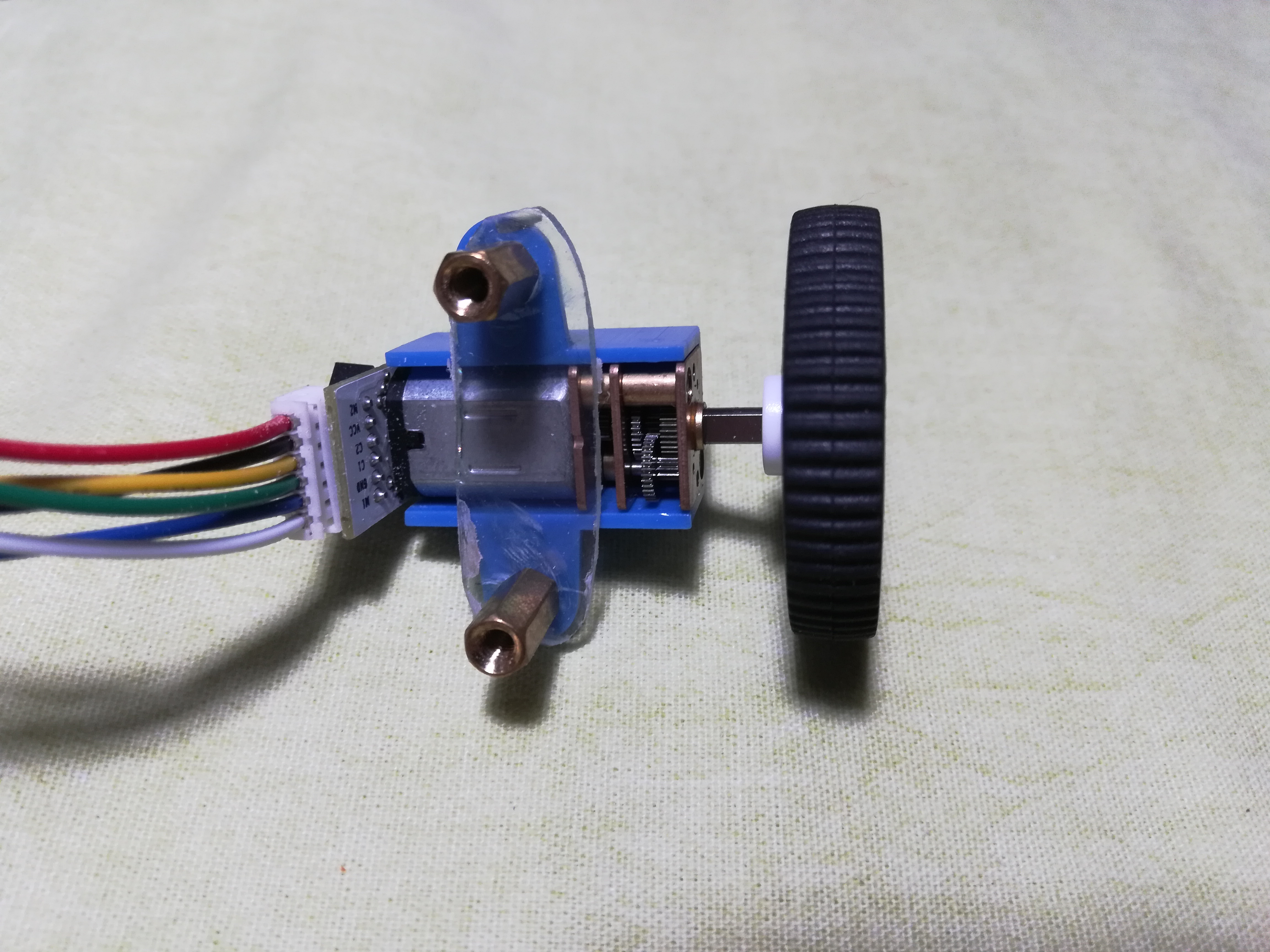
As the image shows, this is not difficult. Just assembly the wheels into the motor shaft, then the motor inside the plastic support. Then the CD plate with the screws attached to the metal extensors to make everything solid. Be sure to add the wires at the connector.
Chassis preparation
Little modification in the chassis may be needed in order to make stuff fit.
Let's first see the result of this step at the image below:
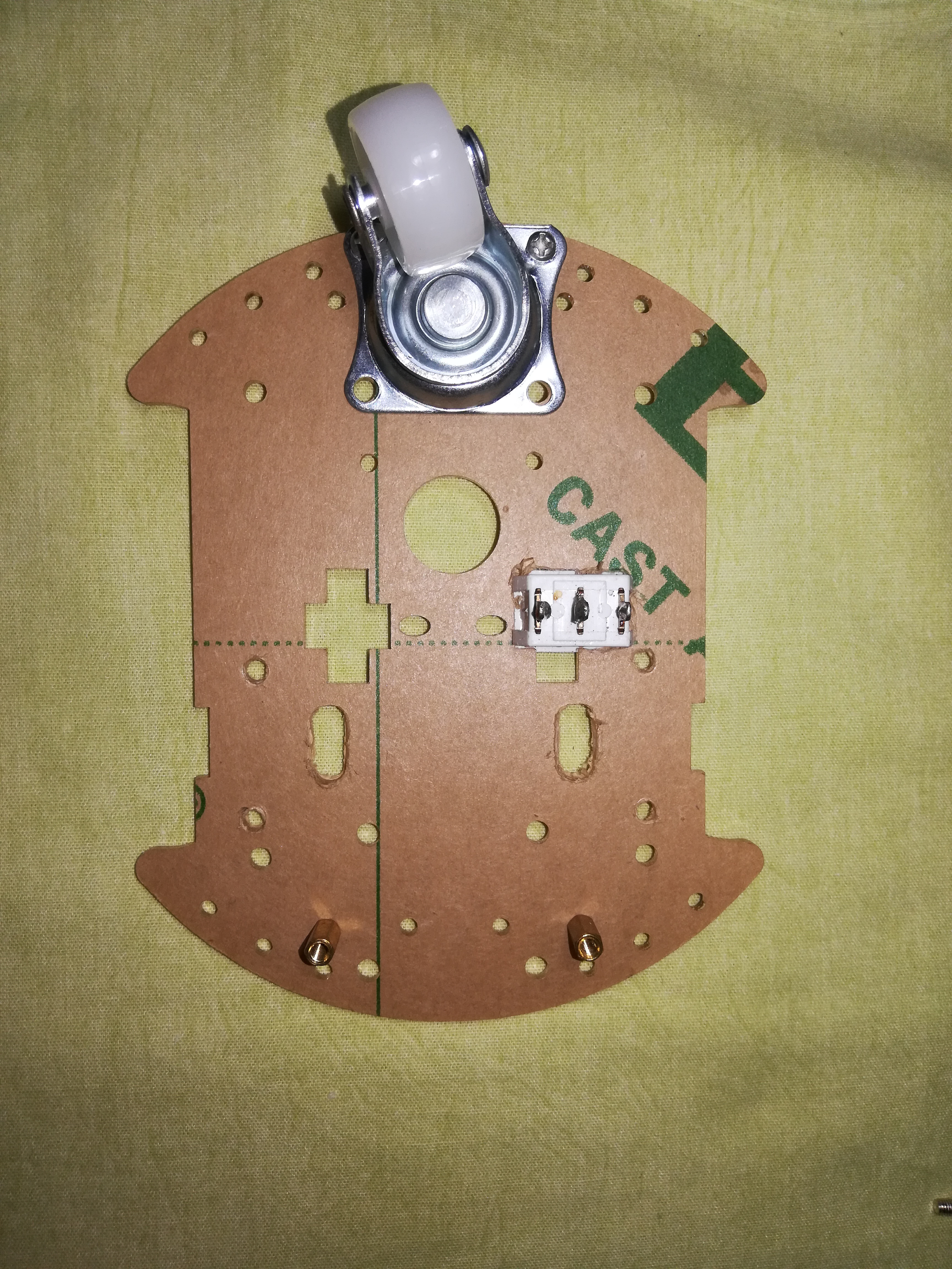
As you can see, our power switch (white rectangle) is in a hole widened for it. Other holes were made to screw the motor extensors and the rectangular holes were widened. The rectangular holes were widened because previously the motors would not be fixed with the extensors, thus you don't need to widen it.
At the backward part of the robot goes the universal wheel (note that this is fixed with just two screws). In addition, put those small metal extensors at the front part of the robot as in the image.
Motor fixation
Once the chassis is ready for the motor, put it. Also just fix the IR sensor at those metal extensors you put in the front of the robot. See the result:
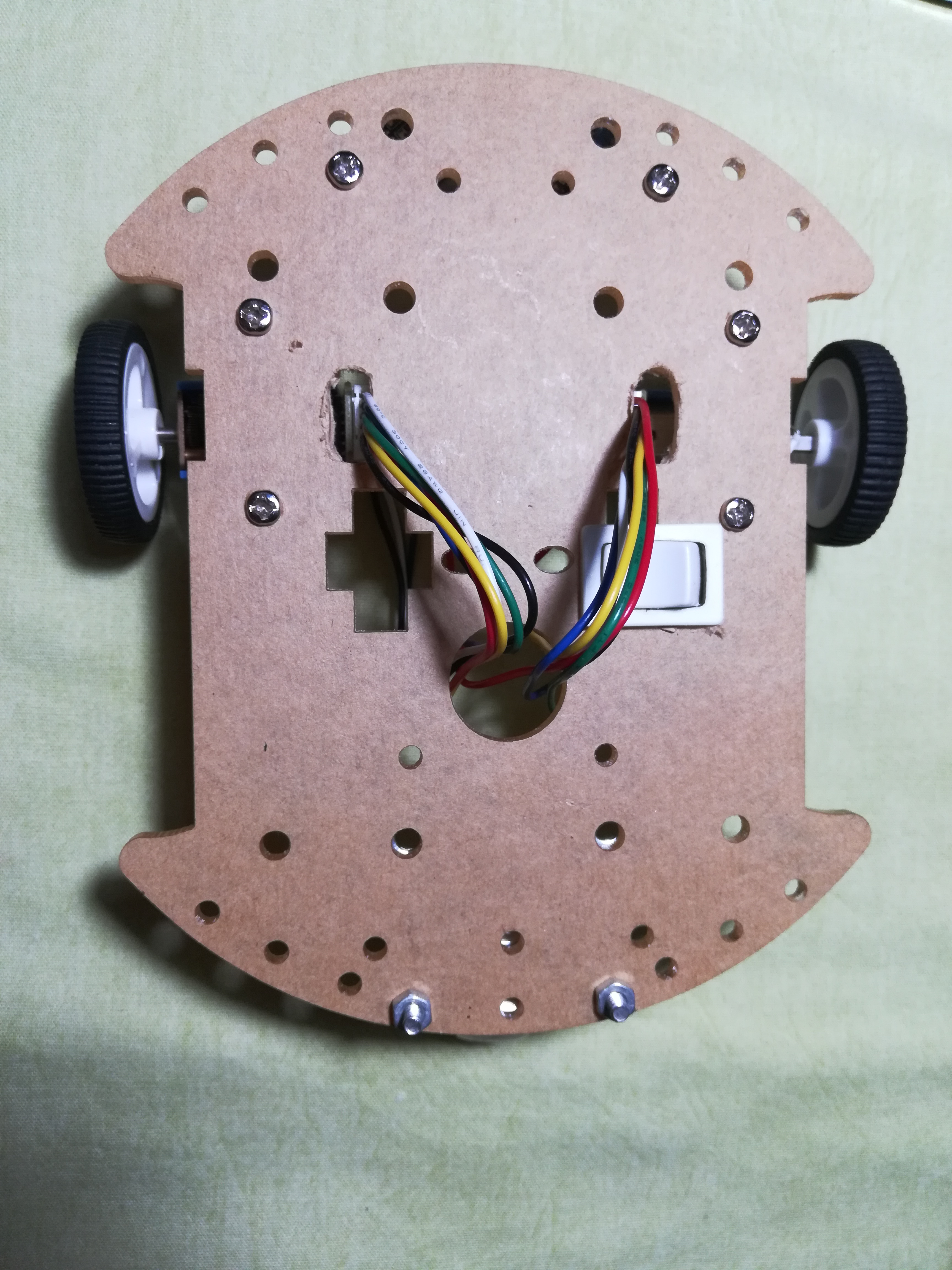
Now this seems like a robot isn't it? The motor wires are connected nowhere.
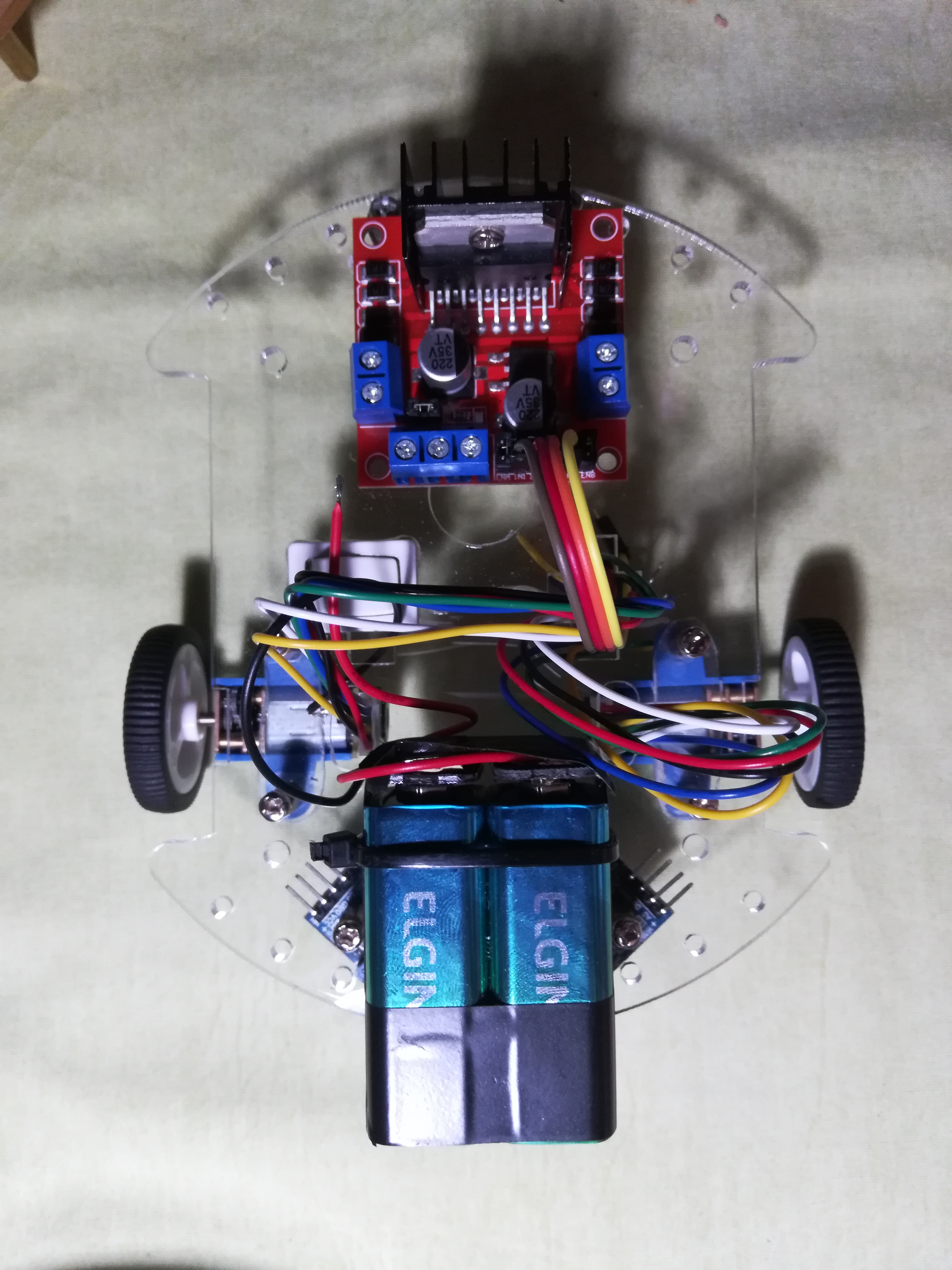
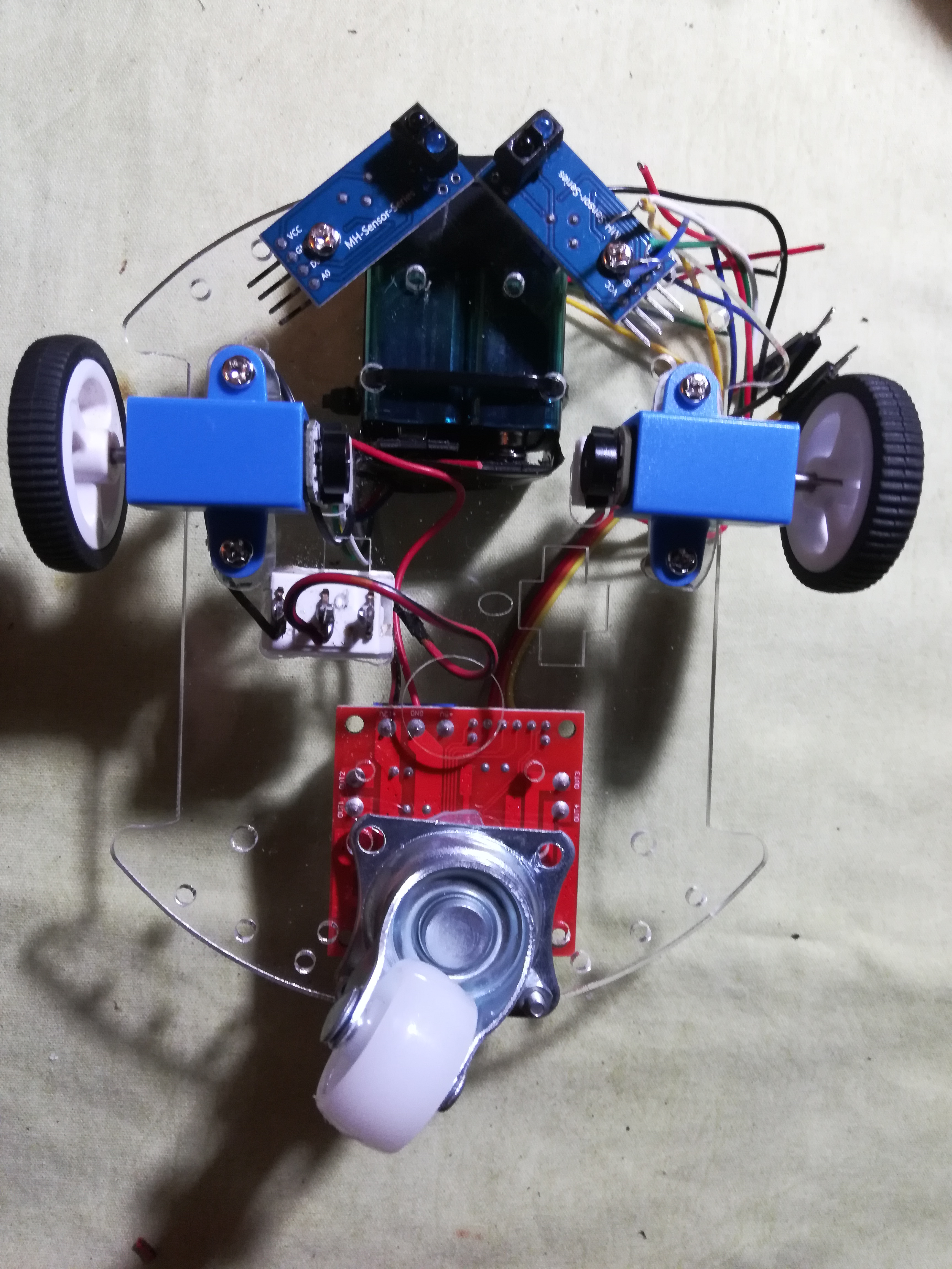
Battery and motor driver positioning
Put the battery a little ahead of the motors and the motor H bridge driver a little ahead of the universal wheel. This way the center of mass of the system should be almost aligned with the motors but a little behind it. Once you are satisfied with stuff positions, fix it! See the image with the result:
 |
 |
|---|---|
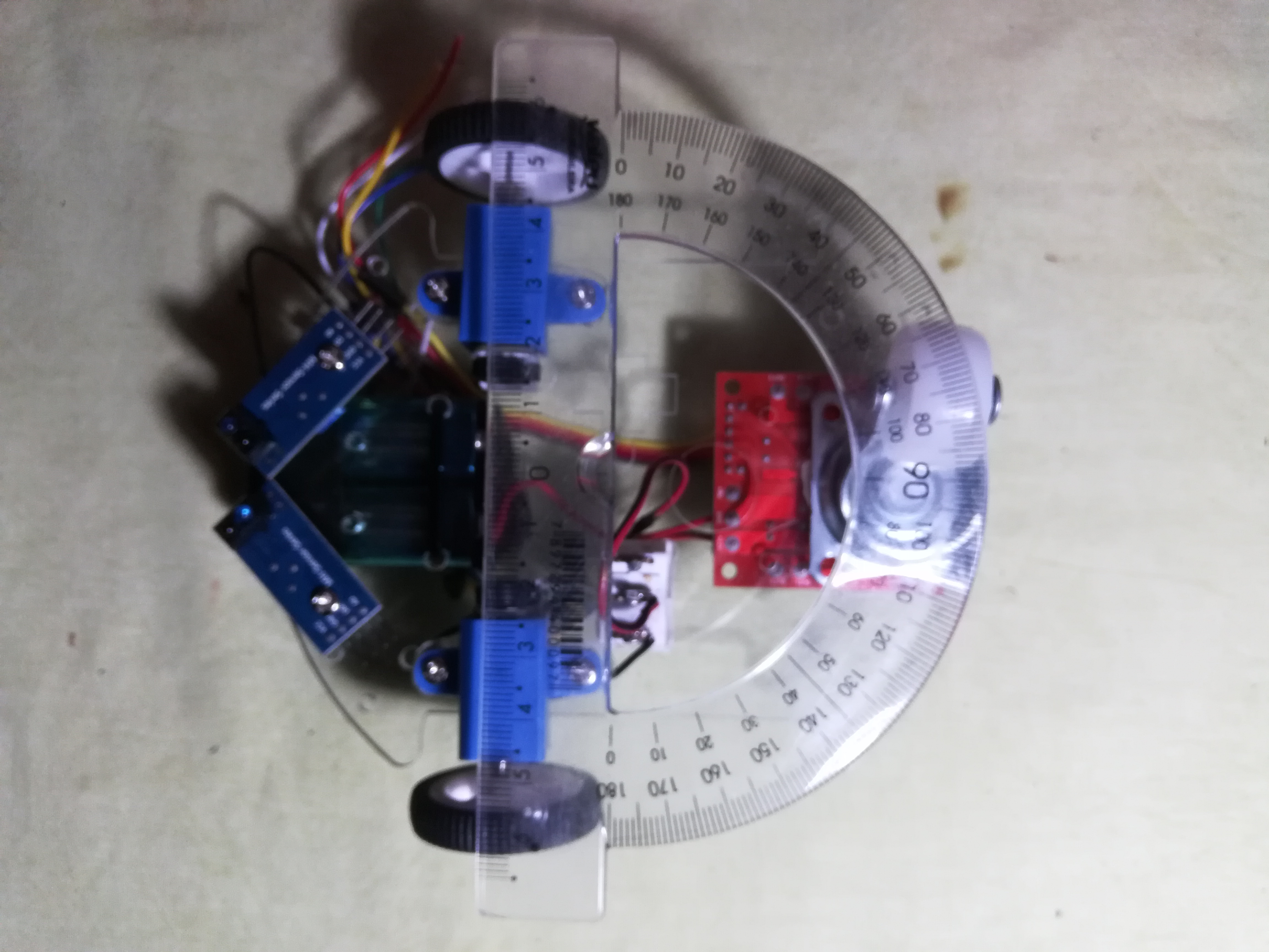
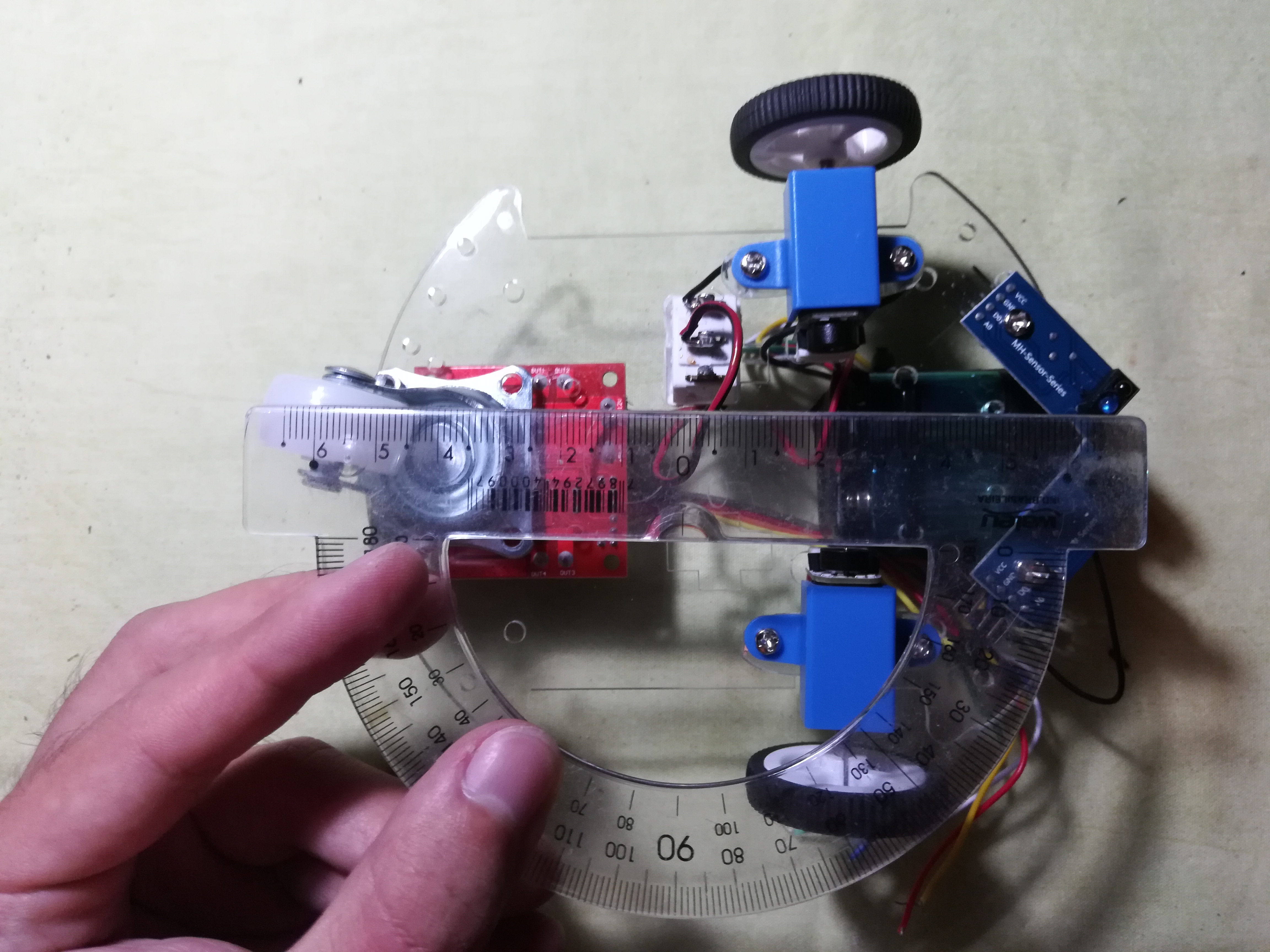
Check-up
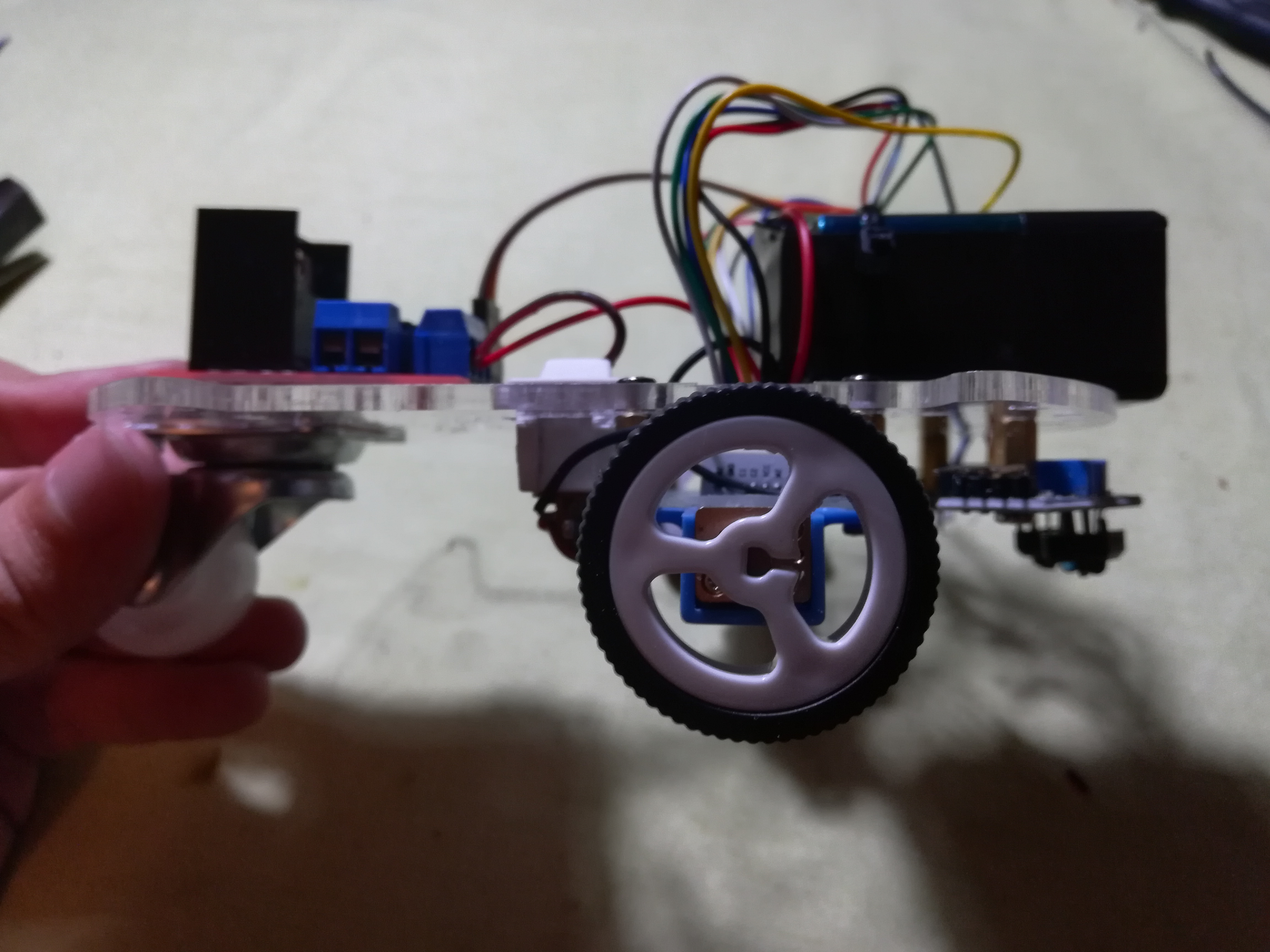
The motors' wheels distance is 12cm as in the image. The upper surface of the motor wheel is at the same plane as the surface of the upper part of the chassis as in the image.
Distance from the center of the universal wheel axis to the motor axis is 6.5cm and distance from the motor axis to the center of the wheel at the universal wheel is 8.5cm as in the image
CLARO QUE O CHECK-UP NÃO VAI FICAR ASSIM.