Motor mathematical modeling
The Brainiac DC Motors mathematical modeling.
The DC motor model is a well-known model studied by roboticists from all over the world. If you never saw it, we strongly recommend you to study it first at this tutorial.
Special thanks to my friend Igor Novais that helped us with modeling this DC motor.
The block diagram of this motor model that will be used here is this one:
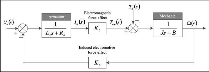 Image from:
 We will start modeling the decoupled system, considering just the motor itself, without the robot's influence. Then we will consider the robot influence and finally we will estimate the covariance matrix of this model. Thus, the modeling will be done step by step, in this way:
- Decoupled system.
- Parametrizing the decoupled system.
- Adding robot inertia.
- Estimating robot inertia.
- Making the model stochastic.
Decoupled system
The decoupled system is the most basic model we can make, which is basically the block diagram previously shown. However, some assumptions and modifications are needed. The inductance parameter (L), will not be considered, this is commonly made as L is too small compared to the inertial parameter (J) "making J a dominant pole". Also, the motor has a reduction, this reduction could be ignored leading to different constants when parametrizing the model. But we preferred to treat that separately. Finally, we assume that no external forces are acting at the motor.
Thus, our motor model block diagram looks like it now:
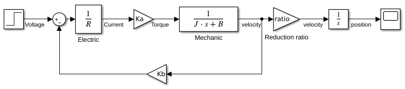
All set, we just need to parametrize it now.
Parametrizing the decoupled system
Using the motor datasheet or factory specification we can calculate all the parameters except the inertial parameter (J). Those factory specs were shown at motor description and the useful ones is shown below again:
- Reduction Ratio: 1:100
- No-load current (): 60mA (verified)
- No-load speed (): 220rpm (verified)
- Stall current (): 450mA
- Stall torque (): 1.5kg*cm
Before using those values at any calculation, be sure to convert the units to SI. We can see that the ratio comes very straight forward, being . The stall specs is easy to use as well since the velocity is 0 eliminating the system feedback. Thus,
Then, we should use the no-load specs using the Final Value Theorem since they happens when . Lets consider the input as a step to 12V, thus we have these equations to motor speed and current:
Finally, to find the and just solve this system of equations:
The solution:
The last parameter remaining is the inertial parameter (J) that does not affect the final value but affects the transient response. To find the J value we simply got the step response for 10.3V input and fit the best J value. The responses are at the image below:
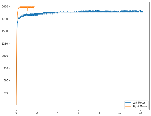
FAZER UM GRÁFICO MELHOR E COLOCAR A RESPOSTA DO AJUSTADO.
The best suitable value to it was .